ICAM V26 Release
These release notes describe the most significant V26 enhancements and problem corrections.
We hope you enjoy your new release of the Vericut Icam products and we sincerely welcome your feedback.
Systems and Packaging
Product Availability
System Manufacturer
O/S Minimum Requirement
Microsoft Windows 64-bit
10, 11, 2016, 2019, 2022, 2025
Important
V26 includes changes in the database format for PP, CE, and VM objects. A V26 database cannot be used with a V25.x run-time. If you have a QUEST developer license, please ensure that you upgrade all your client installations (developer and run-time).
Vericut Icam software is not available for UNIX systems. An Icam database created with V20 or earlier on a UNIX system is fully compatible with Vericut Icam software running on Windows systems.
Licensing
The license server now automatically remove clients from the pool if they have not taken licenses in the last 30 days.
Productivity Tools
QUEST Developer’s
Soft clamp status
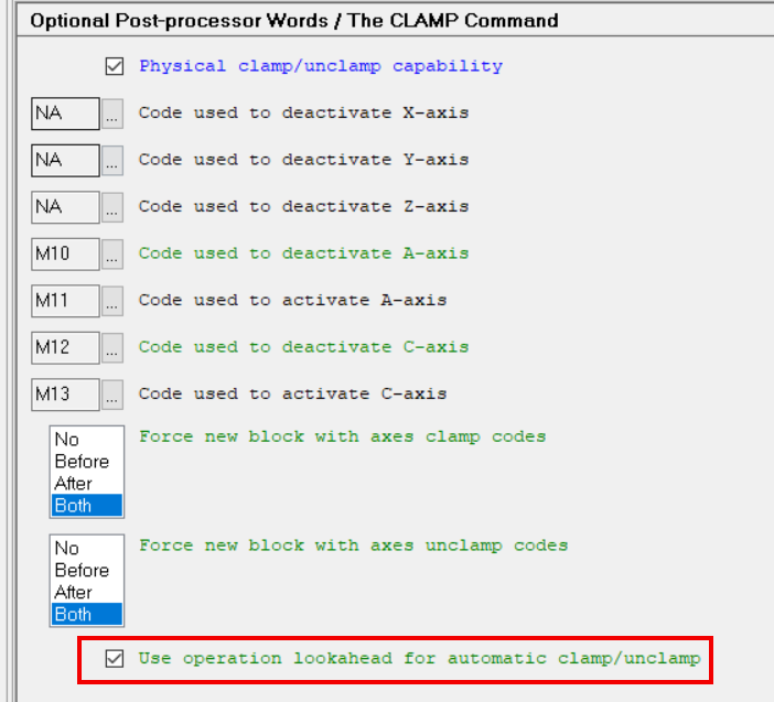
A new question #58 “Use operation look-ahead for automatic clamp/unclamp” has been added to the CLAMP section of the Questionnaire to enable a look-ahead feature at the start of each operation to handle automatic clamping and unclamping.
See “Soft clamp status” in the GENER section below for more information. See below in GENER section for more information
Support for named tools
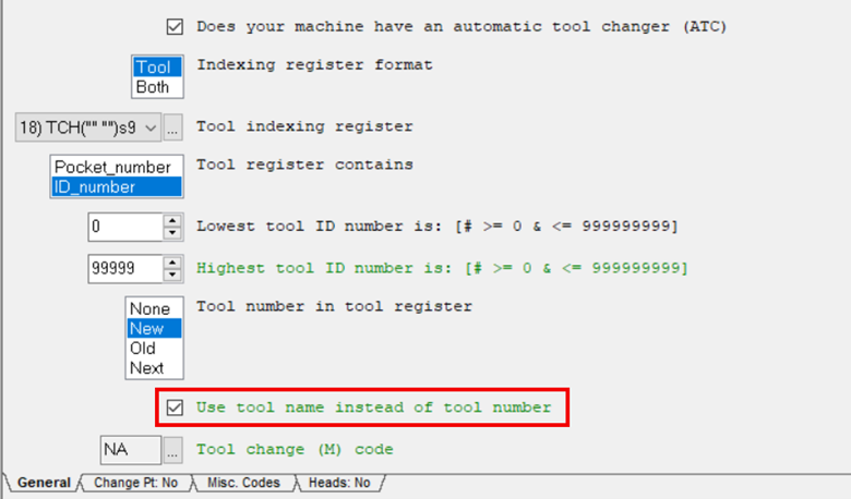
A new question #28.5 “Use tool name instead of tool number” had been added to the Tool Change section of the Questionnaire to support tool change codes that use tool names rather than tool numbers. A special tool indexing register is required to be configured when using tool names.
See “Support for named tools” in the GENER & CERUN section below for more information.
GENER Post-processing
Vericut Project File Use
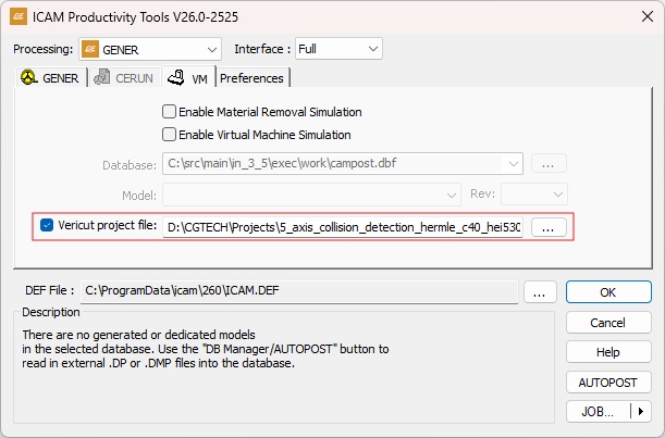
Customers who are using both Icam Post and Vericut can now point the GENER launch panel to a previously-generated Vericut Project file. This will allow GENER to retrieve compensation values to be used during post-processing for a more accurate calculation of travel limits and actual tool lengths.
VO/FORCE integration with GENER
When licensed for both Icam Post and either Vericut Optimizer (VO) or the Vericut Force optimization module, it is now possible to automate feedrate optimization before post-processing. This optimization is applied to the cutter location (CL) data, rather than the G-code.
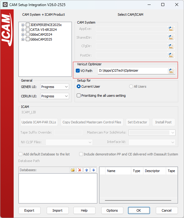
The ICAM Setup Utility, used to integrate with CAM systems, now includes controls to browse for the installation folder of Vericut Optimizer or Vericut Force.
Once the integration is configured, a new tab labeled Optimizer will appear in the GENER launch panel.
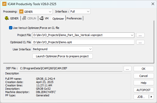
This tab allows users to:
Browse for a previously generated Vericut project file, or
Launch Vericut Optimizer directly if no project file exists.
After optimization is complete, GENER will automatically use the optimized cutter location data as input to the post-processor. This streamlines the workflow by:
Reducing the number of steps required, and
Supporting environments where procedures prohibit modifying the post-processed NC program.
RTA for non-spinning tool (orienting)
When a T-slot tool or a non-symmetrical tool (e.g., an ultrasonic tool) is loaded, the tool must first be moved away from the stock wall to a clearance position before the classic RTA sequence can be generated by moving the tool along the tool axis.
The LINTOL/ROTREF command has new OFSETL, LEFT and RIGHT parameters, which define an extra offset that moves the tool out of the slot or away from the wall. The offset can be specified either as an OFSETL vector, which defines the direction and amount of the offset, or as a scalar, where a LEFT or RIGHT keyword indicates the direction of the offset. The same values are used in reverse on entry, to approach the start of the cut from the side.
GENER Soft clamp status
A new look-ahead algorithm provides improved automatic clamping and unclamping of rotary axes before and after indexing. GENER will automatically turn off auto-clamping in operations where all axes are moving simultaneously.
A new ALL keyword in CLAMP syntax can be used to apply or remove clamps on all axes having physical clamp/unclamp codes.
New macro variables describe the current clamp/unclamp status of all machine axes:
$CLAMPM array
$CLAMPM{XYZUVWE}, $CLAMPM{ABC[TH]} and $CLAMPM{ND}
GENER detailed traces
The multi-level trace option available in the Debug tab of the GENER Tools → Preferences dialog now offers more useful information to help users understand how GENER takes decisions during post-processing.
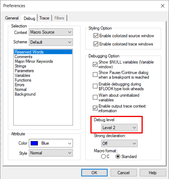
Setting the debug level to Level 2 will generate new debugging information for the following:
Cycles
Circular interpolation
Threading
SmartCUT look-ahead
Improved LCS/AUTO
A new algorithm has been developed to improve the automatic generation of tilted plane codes (LCS) during 5-axes hole-making operations with multiple tool axis orientations. LCS/AUTO also works better now with motions generated by optimization features such as SmartPATH, Path Planning and Rotary Turn-Around.
SmartPATH safe entry/exit
A new SMARTP command (SMARTP/SAFPOS,(ON|OFF)) is now available to control the start and end of SmartPATH-generated motion sequences at tool change or home reference positions. It provides the definition of a bounding geometry to facilitate safe approach to the stock and allows for better control of tool length compensation during these motions.
Fast $FCLINFO look-ahead
The $FCLINFO() function is used to obtain information about upcoming CL data. It is similar to $FINFO(), except it performs a selective look-ahead, therefore it executes significantly faster.
When used with no arguments in the Machine Startup Macro, $FCLINFO() returns a sequence representing a map of all the operations in the CL data file. The first element in this sequence is the number of collected operations. The remaining elements provide various other information.
When used with ID or CLREC as the first argument, $FCLINFO() returns information specific to one particular operation.
$FCLINFO(ID,op_nb)
$FCLINFO(CLREC,op_cln)
The following table summarizes the information returned by $FCLINFO() when used this way:
OPDATA(1)
REAL
ID number
OPDATA(2)
REAL
CL record number of the OPTYPE command
OPDATA(3)
REAL
CL record number of the next OPTYPE command (0 if not found)
OPDATA(4)
REAL
OPTYPE coded (same as $OPTYPE)
OPDATA(5)
REAL
Operation type: 3, 32, 320, 5
OPDATA(6)
REAL
CYCLE type: as $CYTYPE
OPDATA(7)
REAL
CL record number of the first cutting GOTO
OPDATA(8)
REAL
CL record of the last cutting motion
OPDATA(9)
REAL
Last cutting motion is followed by TC/HOME (0|1)
OPDATA(10)
REAL
Tool number used in this operation (location in $TLTAB())
OPDATA(11)
STRING
Operation name
GENER & CERUN
Performance Improvement
Speed improvement on launching the application or rewinding the run-time process.
Speed improvement when processing long input files and having all trace windows up, as well as increasing the maximum number of traces (from the Tools → Preferences dialog).
Run-time UI Trace Windows
The trace windows quality of text rendering have been improved.
All trace windows can now be zoomed simultaneously using the mouse wheel with the CTRL key.
Support for named tools
A new question, #28.5 has been added to the Machine Description / Tool Change section of the Questionnaire, which allows tool names to be used instead of tool numbers when generating or emulating MCD files.
Tool names can be formatted per CNC requirements using the Register dialog, by defining a register that combines the tool name with the other required characters (e.g., brackets, quotes, etc.). When this is configured in a psot-processor, GENER will output the tool name in place of the register value when issuing the tool register.
The same question and register are also supported when configuring a control emulator (CE) in QUEST. This allows tool names to be retrieved from NC program blocks. NC programs can mix tool IDs and tool names by adding a
REG_TOOLalias in the CE, enabling flexible tool referencing.Diagnostic Event macro
A new Diagnostic Event macro is available for PP and CE. When used with a Virtual Machine model, use the PP/CE macro to also catch the VM diagnostics.
A diagnostic macro is executed whenever a diagnostic (message, warning, error, fatal) is processed. The macro will be called even if the diagnostic is disabled, however it will not be called if all diagnostic processing is disabled via the $ERRMSG system variable. The macro is called before the diagnostic is output and counted in the statistics. The diagnostic message can be modified, deleted or additional diagnostics inserted using the diagnostic macro feature.
Diagnostic macros have the following $P variables:
- $P01:
Flag (0:Disabled/Delete, 1:Enabled/Output)
- $P02:
Diagnostic number
- $P03:
Severity number
- $P04:
Diagnostic occurrence
- $P05:
Diagnostic message
$P1 controls the diagnostic macro. On entry, $P1 represent the enabled status of the diagnostic number. When the macro terminates, the value of $P1 is checked to determine if the diagnostic should actually be output. Setting $P1 to zero will cause the diagnostic to be discarded. Setting $P1 to any other value will cause the diagnostic to be output to the UI, listing and also counted in the statistics.
$P2 is a real number representing the diagnostic number as defined in the error file. $P2 is can be modified in order to output other diagnostics.
$P3 is the diagnostic severity number as defined in the error file. The severity can be changed by modifying the value of $P3.
$P4 is a real number representing the number of times the diagnostic identified by $P2 has been generated. The first occurrence of a specific diagnostic will have $P4 set to 1 on entering the macro. Subsequent occurrences will increment $P4. This variable is read-only.
$P5 is a string containing the formatted diagnostic message text. This variable can be altered in order to customize the message that will be output.
You can generate additional diagnostic messages by coding an OUTPUT command. This command causes the diagnostic message, as identified by the $P variables, to be output. The $P variables can then be changed, and OUTPUT called again.
Post-processor diagnostic macros must not contain post-processor commands; Control emulator diagnostic macroes must not contain commands that process MCD. Diagnostic macros can modify user global and object variables as well as macro system variables. Diagnostic macros can also use any macro commands excluding those that generate CL records.
The diagnostic macro can be toggled on or off by use of a new $DIAGMAC macro system variable ($TRUE or $FALSE).
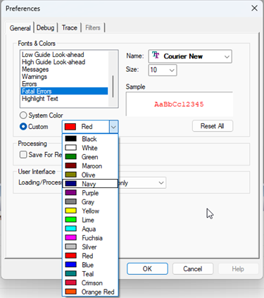
Diagnostic Severity Colors
The four diagnostic severity levels generated by GENER and CERUN — Messages, Warnings, Errors, and Fatal errors — can now each be displayed in a distinct color.
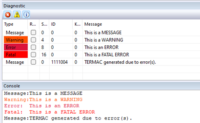
These colors can be customized through the Tools → Preferences dialog in both GENER and CERUN.
Virtual Machine
Tolerance Per Tool
A new method for handling tolerances per tool has been implemented. The updated logic uses the user-defined tolerance for each tool directly. Tolerances can be set on the new Tolerances page or assigned individually to each tool using a custom value.
Tolerance options: A new Tolerances section has been added to the simulation Options dialog. Users can choose between:
Development tolerances for faster execution, or
Production values for more accurate results (with longer run times).
Within each mode, tolerances can be defined for different tool types: Finishing, Semi-finishing, and Roughing. Additionally, users can assign custom tolerances per tool by selecting a Custom Tool Type in the Tool dialog and entering a specific tolerance value.
The logic has been updated to prioritize the new tolerance settings. To revert to the previous behavior, set the macro variable
$TOL251to true. The old logic will also be used automatically when running a post-processor or control emulator version earlier than V26.Multiple spindle and active tools in the same channel
A new $FMSADDTOOL macro function has been created to manage additional activation of tools that can be used to machine the stock in conjunction with the main spindle or main cutting tool. The function syntax is as follows:
The toolaxis_id and the pocket_id specifies the additional tool to be activated or to be disabled. The tool is activated by specifying the part_id on which the tool axis traces should be attached. Specify OFF, or use a part_id value 0, to disable a tool that was previously activated.
![result = \mathbf{\$FMSADDTOOL} \begin{pmatrix} toolaxis\_id, [,pocket\_id], \begin{array}{l} part\_id \\ \mathbf{OFF} \end{array} \end{pmatrix}](../../_images/math/b4f3384fddcf6b542355deaf362990550ad75f51.svg)
Macro Language
XOR Operator
A new “Exclusive OR” operator is now available in the macro processor
Standard macro operator: .XOR.
C++ style operator: ^^
Summary of Macro Functions and System Variables
Module
Variables & Functions
GENER/CERUN
$FMSADDTOOL(toolaxis_id [,pocket_id] ,part_id | OFF)
GENER
$CLAMPM{XYZUVWE}, $CLAMPM{ABC[TH]}, $CLAMPM{ND}
GENER/CERUN
$DIAGMAC
Integration Tools
Integration Tools standalone installation
Customers who need to keep their client (GENER/CERUN/VM) at an older major release (like V25, V24…) are now be able to install newer versions of the CAM integration tools. This allows older ICAM Productivity Tools to integrate with later CAM system releases.
CAM Setup Utility help
Added F1 context help to the CAM Setup Utility.
NX ICAM Template improvement
The cycle name mom_cycle_cam is now output via the CAM parameter on the CYCLE command.
Creo Windchill support
Windchill is a cloud-based Product Lifecycle Management (PLM) system from PTC that integrates with Creo. Icam now supports the manufacturing process, which is loaded from Windchill.
For integration to work with Windchill, first run the setup utility and select your current Creo and Icam product versions. Select the appropriate database, UI preference, and kit. If you are using Windchill, enable the “Using Windchill PLM” checkbox. This will enable integration to work with files loaded from the Windchill environment.
Note that regarding Windchill, the parts are stored in the cloud, so the extractor option to output to the part folder will not function.
PP/CE/Model association
PP and CE have a question to specify the associated Virtual Machine model. A CE can also be linked to a PP. In the extractor, when reading the database, those association will be used to update the PP, CE and VM model selection automatically.
Updated setup utility to find the NX template in the ICAM_APPDATA directory
The NX template used for Icam post-processing is typically customized for each customer, with only minor changes made within the template itself. To allow customers to upgrade the Icam Integration Tools without losing their customized NX templates, a new mechanism has been implemented: templates can now be stored in the
ICAM_APPDATAlocation. This ensures that upgrading the Integration Tools will not overwrite or remove custom templates.To make sure your custom templates appear in the Setup Utility, follow these steps:
Choose one of the following directories:
ICAM_APPDATA directory:
C:\ProgramData\icam\260\clsfIntegration Tools installation directory:
<install path>\Integration\NX\CLSFIn the chosen directory, create a subfolder with the name you want to appear in the Setup Utility.
Copy your custom
.tcland.deffiles into that folder. Make sure there is only one file of each type in the folder.Updated the
kit.macfile for NXAdded macros to handle CSINK diameter changes when a flat-bottom chamfer mill is used. The updated kit now outputs the CSINK diameter, allowing users to insert custom macros that adjust the CSINK diameter based on the tool type — specifically for flat-bottom chamfer mills. This results in improved post-processing output.
Supported CAM Systems
The following is the list of currently supported CAM systems and their versions.
CAM system
Supported versions
3DEXPERIENCE
2015x–2025x
CATIA
V5R21, V5-6R2012–2025
Cimatron
2025
Creo
7-11
FeatureCAM
2017–2025
Fusion 360
2021-2025
GibbsCAM
2024–2026
Mastercam
2019–2025
NX
12, 1847, 1872, 1899, 1926, 1953, 1980, 2007, 2206-2412
PowerMill
2021–2025
PQRs
The following is a partial list of corrections made to V26. Corrections due to internally generated problem reports, user interface problems, as well as customer reports of an obscure nature, are not reported here. Many of these corrections are also available in updated releases of older versions (the updated release number is listed in brackets at the end of the description).
PQR |
Description |
|---|---|
006794 |
Resolved an issue with indexing CL records to output MCD for DELMIA simulation. [V25.1-2523] |
006758 |
Fixed a CERUN issues with SIEMENS MCALL. If the CYCLE following the MCALL command is not recognized, the MCALL would define the next non-modal CYCLE as a new modal call. [V25.1-2523] |
006780 |
Clamp code for lathe C2 axis was not implemented in CERUN. Siemens $P_GG[29] was not mapped to the proper CODE identifiers for lathe (radius or diameter programming). [V25.1-2520] |
006775 |
Fixed an issue with the QUEST Machine model builder where hidden object would reappear after double clicking a node in the navigator. [V25.1-2518] |
006754 |
Fixed a crash in GENER when processing a circular motion with a spiral component. [V25.1-2514] |
006743 |
Fixed an issue with FLOOK-type debugging where some diagnostics were not output and diagnostic count was not matching the number of output to console. Diagnostics output during FLOOK-type look-ahead are now tagged with the “(LKA)” mention. [V25.1-2512] |
006724 |
Fixed an issue where a single machine type developer would not show the proper questions in some QUEST sections. [V25.1-2508] |
006543 |
GENER was generating an “Invalid continuous motion modifier word in APT file” error message when processing 2d circular motion with TLON,GOFWD/(CIRCLE/..),ON,(LINE/...) when AUTOPS is programmed on non XY plane circles. [V25.1-2506] |
006720 |
Fixed the Package Job feature that was not working well with languages other than English. [V25.1-2505] |
006710 |
Fixed an issue where GENER input trace would remain in the look-ahead color after the processing went back to normal mode. [V24.2-2505] |
006714 |
$FMX was only supporting an array argument. It now can accept a sequence as well. [V24.2-2504] |
006709 |
Fixed multiple issues related to the VM tool profile creation. [V25.0-2502] |
006700 |
Aptsource input was no longer recognizing “.” without digits as a zero. [V25.0-2450] |
006694 |
Fixed the PPFUN/12,NEXT,n,2 command, which would not force the rotary out in certain conditions. Fixed the GENER PPFUN controller tab window, which would not show the proper status for PPFUN/12,NEXT. [V24.2-2449] |