Other CL File Commands Affecting Output
There are quite a few other commands generated in the cutter location (CL) file that, although they are not true (or traditional) post-processor commands, will have some effect on the final tape output, as well as on the internal CL file that is generated. The following table lists these commands along with their associated CL record class:subclass value.
1000:isn
2000:1038
2000:1039
2000:1040
2000:1040
2000:1154
5000:3
5000:4
5000:5 or 5000:6
5000:5 or 5000:6
5000:5 or 5000:6
3000, followed by 5000 or 15000
6000:0
6000:1
6000:3
6000:4
6000:5
6000:6
9000:2
9000:9
9000:10
14000
not applicable
not applicable
not applicable
not applicable
not applicable
Descriptions of these commands can be found in the sections that follow.
The ISN Command
The ISN command creates a 1000 class record identifying the source record number in the originating aptsource file that was responsible for creating subsequent CLDATA records.

ISN records are normally automatically generated when reading an aptsource file unless the ISN_ON_OUTPUT definition file variable is set to “NO”. An ISN command stops further automatic generation of ISN records. Each ISN command creates a 1000 class record with a subclass value (i.e., ISN number) of n.
The TRACUT Command
The TRACUT command defines a matrix transformation to apply to subsequent aptsource. Most CAM systems and APT processors do not pass the TRACUT command to the post-processor, or if they do, it is informational and defines the transformation currently in force.
![\textbf{TRACUT / } \big[\,\textbf{LAST},\big] \, \mathtt{<\!matrix\!>}](../../_images/math/a8d3116bfbb511d18d9bc869783a3a3838bf5b28.svg)
![\textbf{TRACUT / } \big[\,\textbf{LAST},\big] \, \textbf{NOMORE}](../../_images/math/55641dc3c17c6e7811c5cab04a440175e1de8008.svg)
TRACUT/<matrix> denotes the beginning of the block of aptsource to be transformed, while TRACUT/NOMORE denotes its end. The transformation matrix must be defined using an APT standard 12 parameter matrix canonical form (see here). The LAST modifier permits an extra level of transformation to be applied by combining the matrices of the two TRACUT statements.
By default, TRACUT commands in the input aptsource file are not processed. This default behavior can be changed by adding a CONTRL/TRACUT command to the aptsource file or to the kit “insert.apt” file.
The INDEX Command
The INDEX command marks the beginning or end of a block of aptsource that will later be replicated (i.e., copied) using the COPY command. Most CAM systems and APT processors do not pass the INDEX and COPY commands to the post-processor, or if they do, they are informational.
![\textbf{INDEX / } n \,\big[,\textbf{NOMORE}\,\big]](../../_images/math/f32ba55225f4f26be64b707e562db1e2c5388121.svg)
INDEX/n marks the start of an INDEX definition, while INDEX/n,NOMORE marks its end. The value n identifies the INDEX definition, which should be unique to the entire aptsource program (a warning is output if an INDEX definition is reused). INDEX definitions can be nested (i.e., contained within each other), but they must not overlap. The COPY command makes additional copies of the aptsource contained within the INDEX definition.
By default, INDEX and COPY commands in the input aptsource file are not processed. This default behavior can be changed by adding a CONTRL/INDEX command to the aptsource file or to the kit “insert.apt” file.
The COPY Command
The COPY command generates additional copies of the aptsource contained within a previously defined INDEX command definition. Most CAM systems and APT processors do not pass the INDEX and COPY commands to the post-processor, or if they do, they are informational.

COPY/n generates count additional copies of the aptsource between a corresponding INDEX/n and INDEX/n,NOMORE, or between INDEX/n and COPY/n if the INDEX block is not closed. Each copy can be progressively translated by an xyz amount, or progressively transformed by a matrix, or progressively rotated in a major plane by an angle, or simply copied as-is.
A COPY command is said to be “nested” if it appears within the range of another COPY. There is no limit on how deeply COPY commands can be nested. The order of matrix multiplication in nested COPY transformations can be controlled using the CONTRL/ALTCPY command. The order of application of TRACUT, TRACUT/LAST and COPY can be controlled using the CONTRL/TRACUT command. These controls are available to allow GENER to duplicate the TRACUT, INDEX and COPY behavior of various APT and CAM systems.
By default, INDEX and COPY commands in the input aptsource file are not processed. This default behavior can be changed by adding a CONTRL/INDEX command to the aptsource file or to the kit “insert.apt” file.
The BLOCK Command
Unique to the 3DEXPERIENCE CAM system, the BLOCK command marks the beginning or end of a block of aptsource that will later be replicated (i.e., copied) using the DEFCOPY and COPY commands.
![\textbf{BLOCK / } n \,\big[,\textbf{NOMORE}\,\big]](../../_images/math/489170d9ddf7b44f728bc222957abd17bbef015e.svg)
BLOCK/n marks the start of a BLOCK definition, while BLOCK/n,NOMORE marks its end (any parameters following NOMORE are ignored). BLOCK definitions can be nested (i.e., contained within each other), but they must not overlap. The value n identifies the BLOCK definition. 3DEXPERIENCE uses this value to indicate the BLOCK definition nest depth; however this is not a requirement. The aptsource within the BLOCK definition is saved but not processed directly. The DEFCOPY and COPY commands replicate (i.e., copy) the aptsource contained within the BLOCK definition.
By default, BLOCK, DEFCOPY and COPY commands in the input aptsource file are processed. This default behavior can be changed by adding a CONTRL/BLOCK command to the aptsource file or to the kit “insert.apt” file.
The DEFCOPY and COPY Commands
Unique to the 3DEXPERIENCE CAM system, the DEFCOPY and COPY commands replicate (i.e., copy) the aptsource contained within a previously defined BLOCK command definition.
![\big[ \textbf{DEF} \big] \textbf{COPY / } n, \textbf{AXIS} \,\big[,\textbf{REF}\,\big], \mathtt{<\!matrix\!>}](../../_images/math/baaae3af3fcb6db5ded3554a874d21317c448c75.svg)
Both DEFCOPY/n and COPY/n replicate (i.e., generate a copy of) the aptsource between a corresponding BLOCK/n and BLOCK/n,NOMORE. The copied motion data is transformed by the matrix. The REF keyword is informational only, used by 3DEXPERIENCE to indicate the first copy of the BLOCK definition. 3DEXPERIENCE uses the DEFCOPY command when replicating a BLOCK definition nested within another BLOCK definition; otherwise, the COPY command is used. Both commands have the same syntax and produce the same results.
By default, BLOCK, DEFCOPY and COPY commands in the input aptsource file are processed. This default behavior can be changed by adding a CONTRL/BLOCK command to the aptsource file or to the kit “insert.apt” file.
The FROM Command
The FROM command typically defines a starting or reference position for the upcoming tool path. Depending on QUEST settings for the post-processor, GENER might ignore the FROM command, or process it as a startup or regular motion and/or use the coordinates to define the machine home position.
![\textbf{FROM / } x, y \,\Big[,z \,\big[,i ,j ,k \,\big] \;\big[,\mathit{feed}\,\big]\Big]](../../_images/math/65ef186f59515b7aa7b6bfb40cd5e4b04d161193.svg)
If a feed value is specified then a “FEDRAT/feed” post-processor command will be generated first, regardless of QUEST settings for the FROM command.
If an ijk tool axis vector is given when MULTAX is not active, then a “MULTAX/ON” command will be generated next, again regardless of the QUEST settings for the FROM command.
The xyz axes values define the reference point in part coordinates. If the z axis value is omitted it defaults to the last specified value (zero by default). If an ijk tool axis vector is specified, the vector is unitized in the generated CL record. If an ijk vector is not specified but MULTAX is enabled in the CL file, then the CL record will include the last specified tool axis vector.
The FROM command generates a 5000:3 class record as follows:
cln,5000,3,'NONAME',0,x,y,z [,i,j,k];
The GODLTA Command
The GODLTA command instructs the tool to move by a specified relative amount in space.
![\textbf{GODLTA / } dt \,\big[,\mathit{feed}\,\big]](../../_images/math/24c3dde17b38df969bbaa97a4332c78ef0c8939b.svg)
![\textbf{GODLTA / } dx,dy,dz \,\big[,i,j,k \,\big] \,\big[,\mathit{feed}\,\big]](../../_images/math/09a164f4c6cc0ed9d7478c2887f18407f87d2680.svg)
If a feed value is specified then a “FEDRAT/feed” post-processor command will be generated first.
If an ijk tool axis vector is given when MULTAX is not active, then a “MULTAX/ON” command will be generated next.
The dt value specifies the relative amount to move along the current CL tool axis. If MULTAX is not enabled the dt value is applied along the positive z part axis.
The dx, dy and dz values specify the relative amount to move in the part coordinate frame. If an ijk tool axis vector is specified, the vector is unitized in the generated CL record. If an ijk vector is not specified but MULTAX is enabled in the CL file, then the CL record will include the last specified tool axis vector.
The GODLTA command generates a 5000:4 class record as follows, where xyz define the absolute coordinates of the end-point of the motion:
cln,5000,4,'NONAME',0,x,y,z [,i,j,k];
The GOTO Command
The GOTO command instructs the tool to move to a specific point in space.
![\textbf{GOTO / } x,y \,\Big[,z \,\big[,i,j,k \,\big] \,\big[,\mathit{feed}\,\big]\Big]](../../_images/math/550eab79b78fd3f74497d223b4032f2ea7ac57ae.svg)
If a feed value is specified then a “FEDRAT/feed” post-processor command will be generated first.
If an ijk tool axis vector is given when MULTAX is not active, then a “MULTAX/ON” command will be generated next.
The xyz axes values define the end point of the motion in part coordinates. If the z axis value is omitted it defaults to the last specified value (zero by default). If an ijk tool axis vector is specified, the vector is unitized in the generated CL record. If an ijk vector is not specified but MULTAX is enabled in the CL file, then the CL record will include the last specified tool axis vector.
The GOTO command generates a 5000:5 class record as follows:
cln,5000,5,'NONAME',0,x,y,z [,i,j,k];
The CONT Command
The CONT command is identical to the GOTO command in that it instructs the tool to move to a specific point in space. The CONT command however is used to define a continuous series of motion points, continuing from a prior GOTO or CONT command. The CONT syntax is identical in all respects to the GOTO command:.
![\textbf{CONT / } x,y \,\Big[,z \,\big[,i,j,k \,\big] \,\big[,\mathit{feed}\,\big]\Big]](../../_images/math/336bdfaa68427b5dab7dff2f6d28187018784c5f.svg)
Including a feed parameter or introducing multi-axis data midway through a continuous motion sequence will cause a break to a new CL record.
A maximum of 80 xyz motions will fit on a single 5000 class motion record. A maximum of 40 xyzijk motions will fit on a single record when MULTAX is enabled. If there are more motions than will fit on a single record, continuation 5000:6 records will be generated for the excess motions.
The GOTO…CONT command sequence generates 5000:5 and possibly 5000:6 class records as follows:
With MULTAX disabled:
cln,5000,5,'NONAME',0,x1,y1,z1,…,x80,y80,z80;
cln,5000,6,'NONAME',0,x1,y1,z1,…,x80,y80,z80;
cln,5000,6,'NONAME',0,x1,y1,z1,…;
With MULTAX enabled:
cln,5000,5,'NONAME',0,x1,y1,z1,i1,j1,k,…,x40,y40,z40,i40,j40,k40;
cln,5000,6,'NONAME',0,x1,y1,z1,i1,j1,k1,…,x40,y40,z40,i40,j40,k40;
cln,5000,6,'NONAME',0,x1,y1,z1,i1,j1,k1,…;
The MOVE Command
The MOVE command is identical to the GOTO command in that it instructs the tool to move to a specific point in space. The MOVE command however is used to define a continuous series of motion points, terminated by a final GOTO command. The MOVE syntax is identical in all respects to the GOTO command:
![\textbf{MOVE / } x,y \,\Big[,z \,\big[,i,j,k \,\big] \,\big[,\mathit{feed}\,\big]\Big]](../../_images/math/fd0f4b7ebca432c56d45889b37dd66359422524e.svg)
The MOVE…GOTO command sequence generates 5000:5 and possibly 5000:6 class records as described for the CONT command.
The MOVARC Command
The MOVARC command specifies the center point and orientation of a circular arc to interpolate on the following motion. The arc starts at the current position (i.e., the tool position when MOVARC is coded) and proceeds to the tool position defined by the next GOTO command. This command is valid for all machine types.
![\hspace{.05cm}\Big[\;\; \textbf{INDIRV / } i,j,k \;\Big]](../../_images/math/e3a8e2fba497120f674e2712f0520846ea504c3f.svg)

![\begin{bmatrix}\,\begin{array}{l}
\textbf{MOVE / } x_1,y_1 \,\Big[,z_1 \,\big[,i_1,j_1,k_1 \,\big]\Big] \\
\ldots \\
\textbf{MOVE / } x_n,y_n \,\Big[,z_n \,\big[,i_n,j_n,k_n \,\big]\Big] \end{array}\end{bmatrix}](../../_images/math/4fec1527b64506cf23f5547de8c4896689ff5406.svg)
![\hspace{.48cm}\textbf{GOTO / } x_e,y_e \,\Big[,z_e \,\big[,i_e,j_e,k_e \,\big] \,\big[,\mathit{feed} \,\big] \Big]](../../_images/math/f028485d8ca907a1a65e8fec464a2d82a461d9e0.svg)
or alternately:
![\begin{bmatrix}\,\begin{array}{l}
\textbf{CONT / } x_1,y_1 \,\Big[,z_1 \,\big[,i_1,j_1,k_1 \,\big]\Big] \\
\ldots \\
\textbf{CONT / } x_n,y_n \,\Big[,z_n \,\big[,i_n,j_n,k_n \,\big]\Big] \end{array}\end{bmatrix}](../../_images/math/7c49a364c9bcee25824386c2376579a11ed7f2f4.svg)
The xc,yc,zc parameters define a point on the axis of the circle. The ic,jc,kc parameters define a vector parallel to the circle axis and the direction of rotation about the circle axis using the “right hand rule”, unless a forward direction of motion i,j,k vector is first specified using INDIRV. The radius parameter specifies the radius of the circular surface being machined. The actual radius of the arc is measured from the start point to the axis of the circle.
If a feed value is specified then a “FEDRAT/feed” post-processor command will be generated first.
If ijk tool axis vectors are given when MULTAX is not active, then a “MULTAX/ON” command will be generated next. The tool axis must not change between start and end of the arc in order for the motion to be interpolated as an arc. The tool axis vector need not match the circle axis vector.
The xe,ye,ze axes values on the terminating GOTO define the end point of the arc in part coordinates. If the z axis value is omitted it defaults to the last specified value (zero by default). If an ijk tool axis vector is specified, the vector is unitized in the generated CL record. If an ijk vector is not specified but MULTAX is enabled in the CL file, then the CL record will include the last specified tool axis vector.
If MOVE commands are specified, then the circle will be described by one or more multi-point 5000 class records containing the intermediate points as defined by the MOVE commands and the final point as defined by the GOTO command. Similarly, if CONT commands are specified, then the circle will be described by one or more multi-point 5000 class records containing the intermediate and final points as defined by the initial GOTO command and following CONT commands. Any count or degrees specification on the MOVARC will be ignored. GENER will verify that the points describe a continuous circle with a constant radius (within the defined INTOL and OUTTOL tolerances) before outputting the arc using circular or helical interpolation. Otherwise the points are linearly interpolated as defined.
If MOVE or CONT commands are omitted, the circle may be represented in the internal CL using one or more multi-point 5000 class records, or the circle may be represented by a single 15000 class record. The choice of circle representation is controlled by the *circles* definition variable. GENER will use the current INTOL and OUTTOL tolerances to approximate the arc in the 5000 class records (if using the multi-point format or in the output NC code if the 15000 class arc can not be interpolated at the machine.
With the segmented circle (multi-point) format, the MOVARC…GOTO command sequence generates: a 3000 class record describing the circle drive surface; and 5000:5 and possibly 5000:6 class records describing the given or calculated intermediate points along the arc (see “The CONT Command” for a description of continued multi-point records).
With MULTAX disabled:
cln,3000,0,3,4,9,'NONAME',0,xc,yc,zc,ic,jc,kc,radius;
cln,5000,5,'NONAME',0,x1,y1,z1,…,xe,ye,ze;
With MULTAX enabled:
cln,3000,0,3,4,9,'NONAME',0,xc,yc,zc,ic,jc,kc,radius;
cln,5000,5,'NONAME',0,x1,y1,z1,i1,j1,k1,…,xe,ye,ze,ie,je,ke;
With the unsegmented circle format, the MOVARC…GOTO command sequence generates a 3000 class record describing the circle drive surface and a 15000 class records describing the complete arc. No tool vector information is included on the 15000 class record because a change in tool axis is not permitted with circular or helical interpolation.
cln,3000,0,3,4,9,'NONAME',0,xc,yc,zc,ic,jc,kc,rmovarc;
cln,15000,0,4,13,'NONAME',0,xc,yc,zc,ic,jc,kc,ractual,angle,xe,ye,ze;
The DNTCUT and CUT Commands
The DNTCUT and CUT commands are used to inhibit the output of one or more motion records. These commands are entered without parameters.


When DNTCUT is encountered, motion commands are no longer written to the CLDATA file.
When CUT is encountered, the last motion record is output. This feature is normally used by APT programmers for intermediate positioning when dealing with ambiguous startup motions.
The DNTCUT and CUT command generate 6000:1 and 6000:0 class records (respectively) as follows:
cln,6000,1;
cln,6000,0;
The TOLER, INTOL and OUTTOL Commands
These commands are used to indicate part tolerances. They are generally used by APT and CAM systems to determine intervals while approximating features such as circles. More intermediate points (or verification points) are generated when tolerance is increased. GENER uses the tolerance information to ensure that the verification points are within tolerance of the desired feature. If the feature (such as a circle defined by a 3000 class CL record) is not within tolerance of the verification points, the circle record is output using the verification points.
![\textbf{TOLER} \hspace{.4cm} \textbf{ / } \mathit{tol_1} \,\Big[,\mathit{tol_2} \,\big[,\mathit{tol_3} \,\big]\Big]](../../_images/math/637000352e2030377cfb853d0432931bf7c8e663.svg)
![\textbf{INTOL} \hspace{.52cm} \textbf{ / } \mathit{tol_1} \,\Big[,\mathit{tol_2} \,\big[,\mathit{tol_3} \,\big]\Big]](../../_images/math/3b58b0f0017575931a93e160a3686e207bd7a47b.svg)
![\textbf{OUTTOL / } \mathit{tol_1} \,\Big[,\mathit{tol_2} \,\big[,\mathit{tol_3} \,\big]\Big]](../../_images/math/e37c59b4f26c94b8496ca56427b76a955acabab2.svg)
The TOLER, INTOL and OUTTOL commands generate 6000:3, 6000:4 and 6000:5 class records (respectively) as follows:
cln,6000,3,tol1[,tol2[,tol3]];

cln,6000,4,tol1[,tol2[,tol3]];

cln,6000,5,tol1[,tol2[,tol3]];
The CUTTER Command
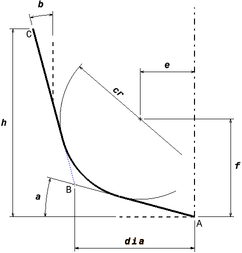
The CUTTER command is used by APT and CAM systems to define tool geometry. The tool diameter is used by GENER to simulate constant surface speed (CSS) and for automatic tool pocket selection (based on tool id and tool diameter).
![\textbf{CUTTER / } \mathit{dia} \,\Big[,\mathit{cr} \,\big[,h \,\big]\Big]](../../_images/math/76e6f1cf7656bd942d8a7891ca3937d8db4c1e07.svg)

The CUTTER command generates a 6000:6 class record as follows, where the cutter dimensions are listed exactly as specified on the CUTTER command:
cln,6000,6,dia[,cr[,…]];
The MULTAX Command
The MULTAX command is used to signal to the CL file generating system that multi-axis motion is desired. Tool axis vectors, indicating the tool axis orientation for each motion, will then be calculated and placed in the CL file along with the regular linear (X, Y, Z) coordinates. This command also will signal to the post-processor that multi-axis data is sitting in the CL file and multi-axis processing should be performed. In order to have rotary axis positioning, MULTAX must be coded.


For machines that do not have rotary axes, CL tool vectors other than the “at rest” tool orientation will not be accepted. For example, if the tool axis is in line with the Z-axis of the machine, the only valid CL vector is (0,0,1). Error messages will be output if an unfeasible tool orientation is requested. MULTAX, therefore, should be used in CL files generated for 4 and 5 axes machines.
One parameter may be coded on the MULTAX command. ON will turn the flag for multi-axis processing on and OFF will cancel multi-axis processing. AUTO will vary the MULTAX state based on the number of parameters specified with GOTO commands. If no option is coded, ON is assumed.
The ROLL option supports an additional 3 numeric elements for each motion, representing the L,M,N components of a cosine vector indicating the wrist orientation for a robot. For numerical control, the roll vector can be used to specify a vector normal to the surface at the tool contact point. This data can be used for 5-axis flank compensation.
The “n” format can be used to specify the number of vector triplets to include with each motion, where 0 (zero) is synonymous with OFF, 1 (one) with ON, 2 with ROLL and higher values are permitted, up to 9.
Tool axis vectors are normalized on input. ROLL vectors are not normalized to allow the specification of other numeric quantities (such as contact position) in the ROLL vector data.
The MULTAX command generates a 9000:2 class record as follows, where “n” is as described above:
cln,9000,2,n;
A special form of MULTAX is available to identify the various triplets of data on a GOTO command, typically to be used with 3D tool compensation when there are 4 or more triplets of data with each motion.

The “n” value identifies the triplet of data, where 1 is the first, 2 is the second and so on. COORD identifies the triplet containing the tool position coordinates (default 1). TLVEC identifies the triplet containing the tool axis vector (default 2). Finally, NORMAL identifies the triplet containing the tool contact normal vector (default 3).
Note that coordinate data cannot be supported in triplet number 2, because the values of this second triplet are always normalized.
The MULTAX/OPTION command generates a 9000:2 class record as follows, where “keyword” is one of the triplet identification minor word codes and “n” is the triplet position:
cln,9000,2,OPTION,keyword,n;
The UNITS Command
The UNITS command is used by the programmer to signal to the CL file generator that the following data and commands have been programmed in a specific units system. The CL file generator will then make any necessary internal adjustments if the units system desired differs from that currently in effect. If it is reading files directly, without having them passed through a CL file generator first, GENER will do the same thing. This command is valid for all machine types.

If the post has dual units, GENER will perform a 20 record look-ahead in the CL file for the UNITS command (the look-ahead distance can be modified via the START_LOOKAHEAD parameter in the ICAM.DEF file). This is primarily to ensure that any startup macros that deal with machine input and output units will be dealing with the right ones. If no UNITS command is coded, GENER assumes that all points, distances and lengths programmed or calculated in the CL file are in the British units system of inches (the default units can be modified via the UNITS parameter in the ICAM.DEF file). GENER further assumes that all output to the tape file will be in the primary units of the post-processor. The post uses various internal values that have been set up for this units system. If a different units system has been used when generating the CL file, the post-processor must be aware of this in order to make its own internal adjustments to the input.
One of the four unit type keywords or a numeric value must be coded on the UNITS command. This command may be used several times with any option in the same program.
The UNITS command generates a 9000:9 class record as follows, where “n” is as described above:
cln,9000,9,173;           UNITS/INCHES

cln,9000,9,174;           UNITS/FEET

cln,9000,9,171;           UNITS/MM

cln,9000,9,172;           UNITS/CM

cln,9000,9,value;         UNITS/value
The TLAXIS Command
The TLAXIS command defines a tool axis vector to use for the next GOTO, MOVE or GODLTA command if a vector is not specifically defined on that command.

If MULTAX is not active, then a “MULTAX/ON” command will be generated first. The ijk tool axis vector will be unitized in the generated CL record.
The TLAXIS command generates a 9000:10 class record as follows:
cln,9000,10,i,j,k;
The FINI Command
The FINI command signals the end of the input CL file. On the main CL file, a FINI ends post-processing. On an included CL file (see “The INCLUD Command”) the FINI marks the end of the included file only; processing continues at the next CL record below the INCLUD command in the calling file.
The FINI command takes no arguments.

The FINI command generates a 14000:0 class record as follows:
cln,14000,0;
The CONTRL Command
The CONTRL command controls various options of the APT front end processor. APT processor function directives can be combined on a single command.
This command does not generate an internal CL record. This command is unique to the APT front end processor. It cannot be specified in a macro; instead it must be specified in the input aptsource file or in the interface kit “insert.apt” file.
Input Card Length
The default input card length is 72 columns unless overridden using the input_width parameter in the definition file. This default can be changed at any time using the CONTRL command.
![\textbf{CONTRL / } \mathit{size} \,\big[,\textbf{OMIT},\mathit{column}\,\big]](../../_images/math/aafc0ef3e3fe23caa586925fbaf66d3188556f78.svg)
The size parameter can be any value from 40 through 256 inclusive. Characters following the size column in input records are treated as insignificant. The OMIT,column option define the size and alignment of a record identification field. A positive value n specifies that the rightmost n columns in a fixed length record are commentary. A negative value indicates left alignment.
For example in the case of Tecnomatix PART to ignore the first 8 columns of the record, you need to code CONTRL/256,OMIT,–8
Output Listing Control
By default all input data is output to a verification file that also lists the assigned ISN and CL data record numbers for the input data. This feature can be controlled from within the source data.

The output of information to the verification file can be suppressed by the CONTRL/NOLIST command. To resume printing, use the CONTRL/LISTON command.
Setting Internal Epsilon
![\textbf{CONTRL / EPSILN}, \mathit{value_1} \,\big[,\mathit{value_2}\,\big]](../../_images/math/7405b4d11c3726e15b7c768a8c190254fe72c99f.svg)
This command allows the user to set the epsilon values used during internal test in GENER. value1 defines the standard epsilon testing value (default is 0.000001) and value2 is the “fuzz” value (default is 0.000000001).
Diagnostic Message Control
By default all diagnostic messages are output to a verification file or to the terminal if a file is not requested (the error_level feature in the definition file can override this default). Diagnostic messages come in two types, warning and error. The appearance of these messages can be controlled from within the source data.

Level 0 (zero) is the default, which allows both warning and error messages to be output. Level 1 (one) inhibits the output of warning messages, while errors still appear. Level 2 inhibits all error messages except severe file input/output processing errors.
Circular Interpolation Direction Control
The direction of circular interpolation with the CIRCLE and SURFACE commands is determined by the direction of the circle axis.
The progression direction differs for CIRCLE and SURFACE; CIRCLE uses the left hand rule, SURFACE uses the right hand rule. The direction of rotation can be seen by making a fist and pointing your thumb along the circle axis. The progression direction follows the curve of your fingers. The left or right handedness of the rule specifies which hand to use.
The CONTRL command can be used to override these defaults.

The CLW and CCLW keywords indicate the required progression direction using the right hand rule. By default SURFACE uses CCLW and CIRCLE uses CLW. Use SMALL if the circle record does not indicate direction, in which case arcs must be less than 180 degrees These defaults can also be overridden using the cir_dir feature in the definition file.
Circle Record Type Control
Two methods of representing circles are supported. Segmented circles (the default) define a circle using 3 or more interpolated points (depending on the program tolerance) in 5000 class motion records. Unsegmented circles define a circle by its end point and included angle in a single 15000 class record.

The numeric values 5000 and 15000 indicate the required circle representation format.
Circle Quadrant Segmentation
The following command affects circular record generation:

The QUAD option forces segmentation of circle records on quadrant boundaries, provided the circle axis is perpendicular to a major datum in the part coordinate system. This produces better results for merging lathes that use the quadrant crossover circular interpolation format.
The NOQUAD option is the default, which produces circle records without special modification.
Multi-point Motion Control
A motion along a curved surface is represented in cldata by a series of point-to-point motions. These continuous motions are identified by a one or more MOVE commands terminated by a GOTO command, or alternately by a GOTO command followed by one or more CONT commands. In either case, there are two methods of representing these continuous motions, controlled as follows:

The MPNT method will pack as many motions as will fit on a class 5000 subclass 5 record, and continue on as many class 5000 subclass 6 records as are necessary. A single 5000 class record can hold up to 240 numeric values, which is equivalent to 80 xyz motions, 40 xyzijk motions, 26 xyzijkpqr motions, etc.
The NOMPNT method will output the first motion on a class 5000 subclass 5 record, and will output the remaining motions individually on class 5000 subclass 6 records.
The choice of method should have no effect on post-processing other than on CLN numbering, however it will affect the user-defined macro matching of motion records. It may be desirable from a macro customization perspective to only have to deal with a single motion per record.
TRACUT Command Processing
By default, TRACUT commands in the input aptsource file are not processed. This default behavior can be changed by coding the following CONTRL command:

OFF is the default. TRACUT commands in the input aptsource file are not processed, but instead passed to the post-processor as-is using a 2000:1038 class record (TRACUT major word). The post-processor will generate a warning diagnostic when it encounters a TRACUT command.
cln,2000,1038,a1,a2,a3,a4,a5,a6,a7,a8,a9,a10,a11,a12;
ON specifies that TRACUT commands in the aptsource file are to be processed. The TRACUT transformations are applied to subsequent motion data. The TRACUT commands themselves are output to the CLDATA as a 1002:1038 class record (ISN comment) for informational purposes, which will be ignored by the post-processor but can be matched by a user-defined macro.
cln,1002,1038,a1,a2,a3,a4,a5,a6,a7,a8,a9,a10,a11,a12;
LAST is the same as ON, but affects the order of TRACUT and COPY processing when these commands are used together. LAST specifies COPY»TRACUT»TRACUT/LAST order, as used by APT-AC and 3DEXPERIENCE (although 3DEXPERIENCE does not support TRACUT/LAST). ON specifies TRACUT»COPY»TRACUT/LAST order as used by CAM-APT-SURF, APT III and APT 360.
INDEX and COPY Command Processing
By default, INDEX and COPY commands in the input aptsource file are not processed. This default behavior can be changed by coding the following CONTRL command:

OFF is the default. INDEX and COPY commands in the input aptsource file are not processed, but instead are passed to the post-processor as-is using a 2000:1039 class record for the INDEX major word and a 2000:1040 class record for the COPY major word. The post-processor will generate a warning diagnostic when it encounters these commands, unless it has been configured in QUEST to support them using CNC subprograms.
cln,2000,1039,…;
cln,2000,1040,…;
ON specifies that INDEX and COPY commands in the aptsource file are to be processed. The COPY transformations are applied to subsequent motion data. INDEX and COPY commands are output to the CLDATA as a 1002:1039 and 1002:1040 ISN comment records for informational purposes, which will be ignored by the post-processor but can be matched by user-defined macros.
cln,1002,1039,…;
cln,1002,1040,…;
BLOCK, DEFCOPY and COPY Command Processing
By default, BLOCK, DEFCOPY and COPY commands in the input aptsource are processed. This default behavior can be changed by coding the following CONTRL command:

ON is the default setting. It specifies that BLOCK, DEFCOPY and COPY commands in the aptsource file are to be processed. BLOCK commands will appear in the cldata as 1002:1154 records, while DEFCOPY and COPY commands will appear as 1002:1040 records. These ISN comment records are ignored by the post-processor but can be matched by user-defined macros.
cln,1002,1154,…;
cln,1002,1040,…;
OFF specifies that BLOCK, DEFCOPY and COPY commands will instead be passed to the post-processor as-is, using a 2000:1154 class record for the BLOCK major word and a 2000:1040 class record for the COPY major word (also used as an alias for DEFCOPY). The post-processor will generate a warning diagnostic when it encounters these commands.
cln,2000,1154,…;
cln,2000,1040,…;
Nested COPY Matrix Multiplication
The order of matrix multiplication in nested COPY commands can be controlled as follows:

ON performs nested COPY matrix processing in 3DEXPERIENCE and APT-AC order. OFF performs nested COPY matrix processing in CAM-APT-SURF, APT III and APT 360 order.
The INCLUD Command
The INCLUD command is used to include additional aptsource data from another file into the main aptsource file. Included files can in turn include other files, to a maximum depth (or nest level) of 10 files. An included file need not end with a FINI command, however a FINI in an included file signals the end of that file’s input, even if the FINI does not occur at the end of the file.
The INCLUD command does not generate an internal CL record. This command is unique to the APT front end processor. It cannot be specified in a macro; instead it must be specified in the input aptsource file or in the interface kit “insert.apt” file. The syntax is as follows:

Relative path file names (e.g., directory\file.apt) are permitted. Paths are relative to the referencing file (i.e., the file containing the INCLUD command).
Environment variable symbolic substitution is permitted in file names. A symbol is specified by a $ character immediately followed by the symbolic name. Surround the symbolic name by brace { } characters if the symbolic name has embedded spaces or to delimit the name from surrounding text.
For example:
INCLUD/'$icam_lib\test.apt'
The PPWORD Command
Icam Post supports over 200 vocabulary keywords. The PPWORD command can be used to define additional words and integer codes if necessary.
The PPWORD command does not generate an internal CL record. This command is unique to the APT front end processor. It cannot be specified in a macro; instead it must be specified in the input aptsource file or in the interface kit “insert.apt” file. The syntax is as follows:

MAJOR and MINOR are used to indicate the type of the keywords being defined. The word,code couplets after the keyword define the new vocabulary words and their associated integer codes. The keywords MAJOR and MINOR are modal and stay in effect for all couplets following the keyword until a new keyword is given. At least one word,code pair must follow the keyword.
MAJOR word integer codes should exceed or equal 1000 for words with parameters. Use an integer code less than 1000 for words without parameters. MINOR word integer codes should not exceed 999.
The following example defines 2 new MAJOR words and one new MINOR word.
PPWORD/MAJOR,BARFED,1092,CATCHR,1091,MINOR,ABSOL,218
The SYN Command
The SYN command is used to define alternate spellings (aliases) for APT commands.
The SYN command does not generate an internal CL record. This command is unique to the APT front end processor. It cannot be specified in a macro; instead it must be specified in the input aptsource file or in the interface kit “insert.apt” file.
The syntax is as follows:
![\textbf{SYN / } \mathit{keyword,keyword} \;\;
{\small \sim}\!\big[,\mathit{keyword,keyword}\,\big]](../../_images/math/f1bdce179f2be04c9ae7392b7e0e1cc823a39a22.svg)
If one of the keywords is a vocabulary word known to GENER and the other is not, any occurrence of the unknown word in the source file will be replaced in the CL data by the known word.
If both of the keywords are known vocabulary, then every occurrence of the left hand word in the pair will be replaced in the CL data by the right hand word in the pair.
It is an error if both keywords in a pair are not known vocabulary.
The following SYN command converts PAINT commands (unknown to GENER) and CLPRNT commands (known to GENER) into REMARK commands. This causes them to be ignored since that is the action GENER takes with REMARK commands.
SYN/PAINT,REMARK,CLPRNT,REMARK
Note that if the order of the “CLPRNT,REMARK” was reversed to “REMARK,CLPRNT”, then every occurrence of REMARK would be processed as a CLPRNT. The order is very important when both keywords are known to GENER.
The format of the standard SYN command has been enhanced to include quoted text strings. This format provides a great deal more flexibility in processing source CL file commands that do not adhere to the APT standard. The format of this SYN command is:

Where text-string is any arbitrary string of text characters and command is any valid GENER command. For example, if the CL file contains a record such as:
$$-> CUTTER/ .5
This command is not recognized by GENER because of the $$ symbol that is interpreted as a comment. The use of the SYN command:
SYN/'$$-> CUTTER','CUTTER'
would change this CL file record into a valid CUTTER command that would then be interpreted by GENER.
The SYNEX Command
The SYNEX command is used to apply a $FEDIT style regular expression substitution to the input aptsource records (see the $FEDIT function)
The SYNEX command does not generate an internal CL record. This command is unique to the APT front end processor. It cannot be specified in a macro; instead it must be specified in the input aptsource file or in the interface kit “insert.apt” file.
The syntax is as follows:
![\textbf{SYNEX / } \big[\,\textbf{LAST},\big]\; \mathtt{'}source\_re\mathtt{'} \;\big[,\mathtt{'}target\_re\mathtt{'}\,\big] \;\big[,\mathit{count}\,\big]](../../_images/math/f6f192e8ccc70b67d1dd9b71cb4445aec80997b3.svg)
By default, all occurrences of the source-re regular expression will be substituted by the target-re regular expression in the input aptsource record. If target-re is omitted, then all occurrences of source-re will be deleted from the input aptsource record. The default action can be changed by specifying a count value. If count is zero, then all matching occurrences are replaced (the default). If count is one (1), only the first match is replaced. Larger values of count cause the specified match number to be changed.
SYNEX by default is applied to each input aptsource line. Specify LAST to apply the regular expression substitution to the final aptsource record, which omits comments, concatenates continued lines, and (except for strings) removes all spacing and converts characters to uppercase.
SYNEX commands are modal and are applied in the order specified. SYNEX/LAST commands are also modal and are applied in the order specified after all non-LAST substitutions.