The ORIGIN Command [MLEPC]
The ORIGIN command is used to specify the machine-tool coordinate system origin in terms of the part reference system (CL file). This command is valid for all machine types.
![\textbf{ORIGIN / } \,\big[\,\textbf{LAST},\big]
\begin{pmatrix} \!,\! \begin{array}{l} \mathtt{<\!matrix\!>} \\ \textbf{ON} \\ \textbf{OFF} \end{array} \end{pmatrix}](../../_images/math/1780b389b7815228862ddcecfd1d80e30a9447df.svg)
Where <matrix> is defined as:
![\big[\,\textbf{INVERS},\big]
\begin{pmatrix} \begin{array}{l} \! \Big[\,x_1,y_1\,\big[,z_1\,\big]\,\Big]\; \big[\,\mathtt{<\!rotation\!>}\,\big] \\
\textbf{MSYS} \,\big[,\textbf{LAST}\,\big] \\
a_1,a_2,a_3,a_4,a_5,a_6,a_7,a_8,a_9,a_{10},a_{11},a_{12} \end{array} \end{pmatrix}](../../_images/math/00f810a6320e09bda48e75d77f0fe56a84fd47ef.svg)
and where <rotation> is defined as:
![{\small \sim}\!\begin{bmatrix} , \begin{pmatrix}\begin{array}{l} \textbf{XYROT} \\ \textbf{YZROT} \\ \textbf{ZXROT} \end{array}\end{pmatrix} ,\mathit{angle} \end{bmatrix} \,
\Big[,\textbf{AT},x_c,y_c \big[,z_c\,\big]\,\Big]\;
\Big[,\textbf{TRANS},x_2,y_2 \big[,z_2\,\big]\,\Big]](../../_images/math/da8d471f7c9a4dc4c69c40e5e74d996880bf6b04.svg)
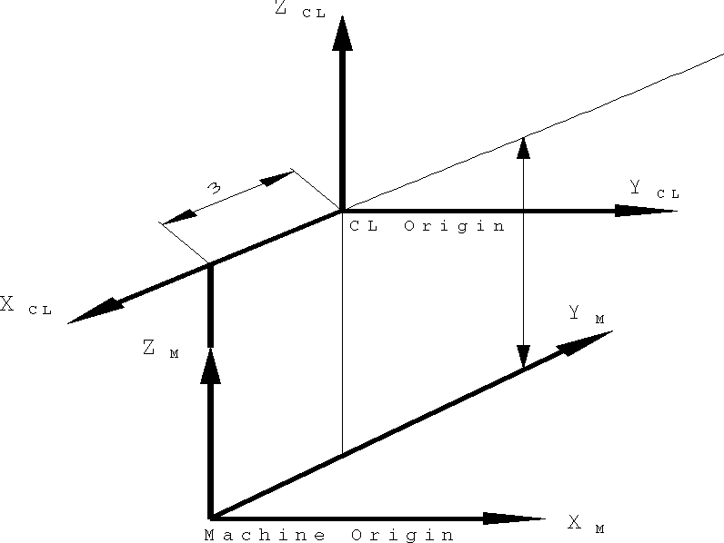
The ORIGIN command indicates the position and orientation of the machine axes with respect to the CL file coordinate system. If an ORIGIN command is not coded, then the CL origin and the machine origin are the same. The purpose of the ORIGIN command is to define a transformation to be applied to CL coordinates to bring them into the machine base coordinate frame.
Two separate transformations can be defined and applied selectively. The LAST keyword is used when defining the second transformation. Omit LAST to define the primary transformation. Either transformation can be made active by coding ON (the default when defined) or inactive by coding OFF. The INVERS keyword applies the inverse of the defined matrix.
![\Big[\,x_1,y_1\,\big[,z_1\,\big]\,\Big] \;\,
{\small \sim}\!\begin{bmatrix} , \begin{pmatrix}\begin{array}{l} \textbf{XYROT} \\ \textbf{YZROT} \\ \textbf{ZXROT} \end{array}\end{pmatrix} ,\mathit{angle} \end{bmatrix} \,
\Big[,\textbf{AT},x_c,y_c \big[,z_c\,\big]\,\Big]\;
\Big[,\textbf{TRANS},x_2,y_2 \big[,z_2\,\big]\,\Big]](../../_images/math/393a7a8e449fed7ffeac07ded02c57834c659924.svg)
The optional x1 y1 z1 components of the matrix definition provide a method of specifying a simple translation between the CL origin and the machine origin. The location specified with this command in CL coordinates indicates the machine origin point. Code a z-axis coordinate value for 3-axis mills, lathes in mill mode or 4 axis wire EDMs. The z-axis coordinate value can be omitted for 2 axis machines and lathes in turn mode.
The coordinate frame can be optionally rotated specifying an axis of rotation and an angle of rotation in degrees. Positive rotation follows the right hand rule. The ORIGIN command rotations define the orientation of the machine axes with respect to their CL counterparts. Compound rotations can be defined as a series of rotations. Rotation is about the origin unless an optional rotation center point is defined using xc yc zc. An additional translation with respect to the as-rotated frame can be defined using x2 y2 z2.
When combining translation and rotation, code the translation components first. For example:
ORIGIN/100,0,0,ZXROT,45,XYROT,60
Code INVERS to have GENER invert the transformation data. When using the INVERS form with ORIGIN, you must define the location and orientation of the part coordinate system with respect to the machine coordinate system.
![\big[\,\textbf{INVERS},\big] \textbf{ MSYS } \big[,\textbf{LAST}\,\big]](../../_images/math/f343d00bcdf45b3de488987053aff2eebb9a02d6.svg)
A second transformation form of the ORIGIN command provides for a general translation and rotation between CL and machine coordinates as defined by the last MSYS command matrix. The INVERS keyword can be used to use the inverted form of the MSYS matrix. The LAST keyword can be used to use the secondary MSYS/LAST matrix instead of the primary one.
![\big[\,\textbf{INVERS},\big] \; a_1,a_2,a_3,a_4,a_5,a_6,a_7,a_8,a_9,a_{10},a_{11},a_{12}](../../_images/math/7dc9fd1be0c7b0e9e8eb43ee1da60e7415400215.svg)
A third transformation form of the ORIGIN command provides for a general translation and rotation between CL and machine coordinates as defined by a 12 parameter matrix. The values are organized as shown in the table below:
Xm
Ym
Zm
Offset
Xcl
1
2
3
4
Ycl
5
6
7
8
Zcl
9
10
11
12
The Xm column defines a unit vector of the machine X axis as seen from the CL coordinate system. Likewise, the Ym and Zm columns define machine Y and Z axes. The offset column is the position of the machine origin, also as seen from the CL coordinate system.
Code INVERS to have GENER invert the matrix. Some matrices cannot be inverted. GENER will output a diagnostic message when this occurs.
ORIGIN commands are not cumulative. Each new ORIGIN command will cancel the effect of the previous command. Therefore, to return the origin to its original status, code ORIGIN/0,0,0 (or ORIGIN/0,0 depending on the machine type) in the CL file. You may also code ORIGIN/OFF or ORIGIN/LAST,OFF to cancel the effect of the ORIGIN, leaving the possibility to reactive the origin later using the ON format.
Example #1
Both of the following ORIGIN commands will define a machine coordinate system rotated 90 degrees CCLW in the XY plane with respect to the CL coordinate system (i.e., machine X axis points along Ycl, machine Y axis points along -Xcl and machine Z axis points along Zcl):
ORIGIN/0,-1,0,0, 1,0,0,0, 0,0,1,0

or

ORIGIN/XYROT,90
Example #2
Both of the following commands will define the machine origin at CL coordinates X=3, Y=0, Z=–7:
ORIGIN/1,0,0,3, 0,1,0,0, 0,0,1,-7

ORIGIN/3,0,-7
Example #3
This last example combines the rotation and translation of the previous two examples:
ORIGIN/0,-1,0,3, 1,0,0,0, 0,0,1,-7